Automatic Menorah - V1
The why
During Hanukkah, my wife's family places a menorah with AC-powered “flickering” lights in the front window of their home. Each day, another bulb must be screwed in manually.
As an engineer, I found it inconvenient to add another light at the end of each day of Hanukkah, so I decided to build an automatic menorah using only analog circuits rather than an MCU for timing control.
The design - clock frequency generator
Finding the best oscillator design required multiple attempts and was probably the most time-consuming part of the project.
Initially, I planned to use a low-frequency crystal oscillator and divide the frequency down using a series of D flip-flops to achieve a 24-hour period. This approach presented two major challenges:
Initially, I planned to use a low-frequency crystal oscillator and divide the frequency down using a series of D flip-flops to achieve a 24-hour period. This approach presented two major challenges:
- Oscillator frequencies are generally quite high, with the lowest commonly available frequencies in the kHz range
- Because the division factor is 2, the clock frequency must be extremely precise
After deciding this was not the best route, I began looking into ring oscillators with RC filters added between each stage to decrease the frequency. This approach is much more configurable than the crystal oscillator method because the RC time constants can be adjusted to change the frequency.
Based on the research I had done, this seemed like a plausible solution, so I built a 3-stage ring oscillator on a breadboard to test the timing. The results were not very good. The rising edge was extremely slow due to the long time constants, which caused transition issues and unstable oscillation.
Based on the research I had done, this seemed like a plausible solution, so I built a 3-stage ring oscillator on a breadboard to test the timing. The results were not very good. The rising edge was extremely slow due to the long time constants, which caused transition issues and unstable oscillation.
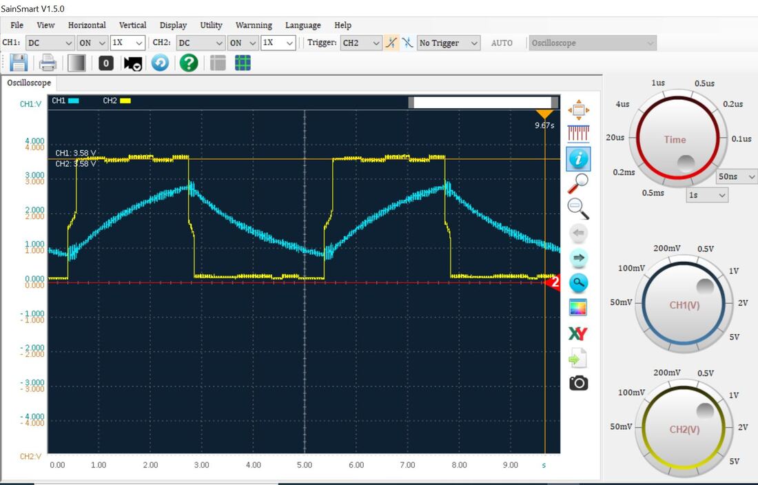 1K Ohm 1mF 3 stage ring oscillator
After switching to a Schmitt trigger oscillator, the rising and falling edges became much cleaner, and the oscillation was considerably more stable compared to the ring oscillator.
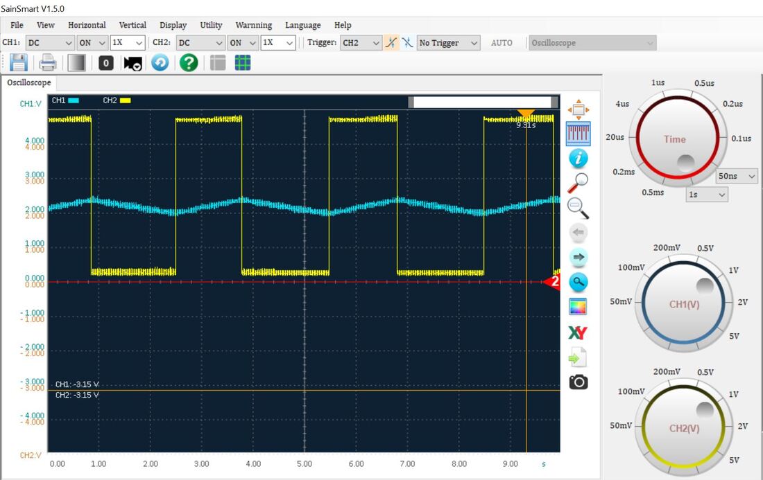 8.2K Ohm 1mF Schmitt Trigger hex inverter 5V
Implementing the design
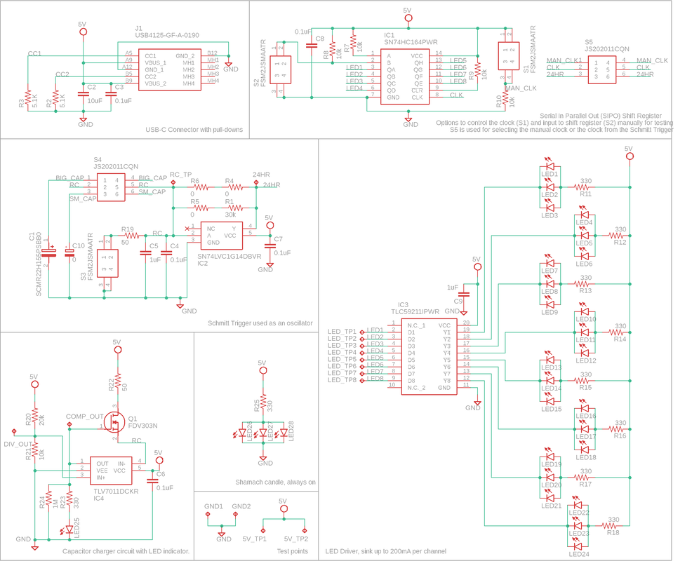
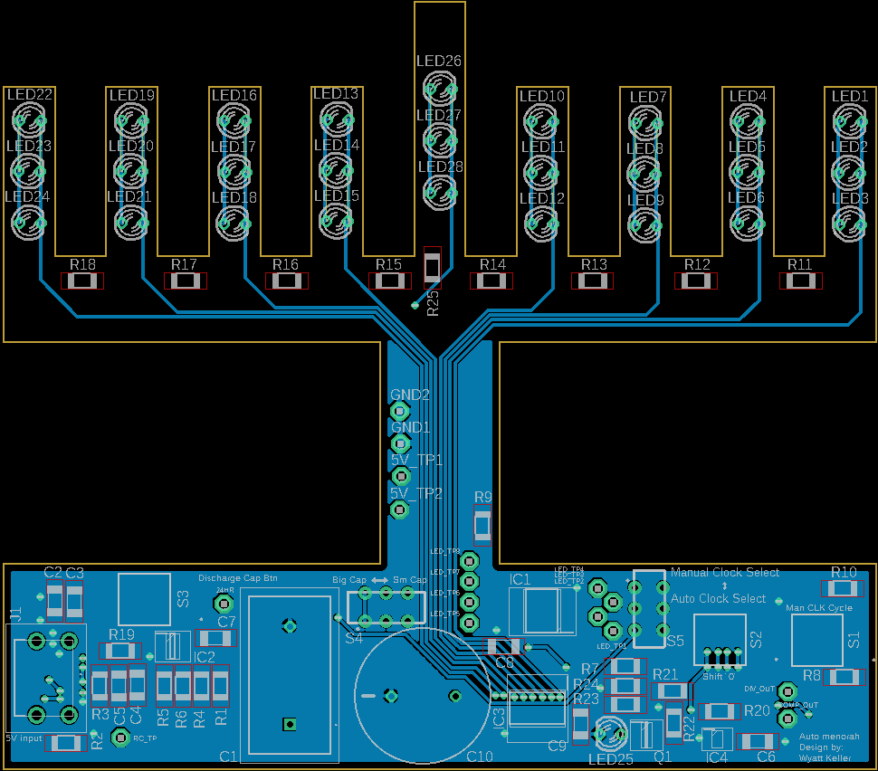
The design is divided into several functional blocks:
- USB-C input for power with 5.1 kΩ pull-down resistors required for proper CC detection by the PSU
- Schmitt trigger with an RC timing circuit for a 24-hour period (SN74LVC1G14)
- Comparator and MOSFET circuit used for the initial charging of the supercapacitor (TLV7011)
- Center candle that remains continuously lit
- Shift register configured for serial-in/parallel-out operation to light one candle at a time (SN74HC164)
- LED driver used to supply enough current for proper LED brightness (TLC59211)
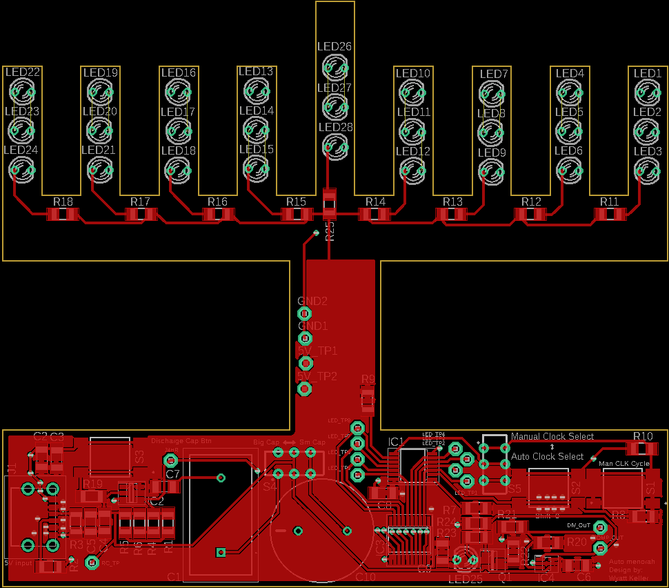
Results from first PCB
After assembling the first PCB, several issues were identified:
- The shift register outputs for the last four LEDs were swapped. The PCB traces were rerouted to correct the issue.
- The 30 kΩ resistor used for the RC time constant was incorrectly calculated. A 150 Ω resistor was temporarily used for testing and data collection.
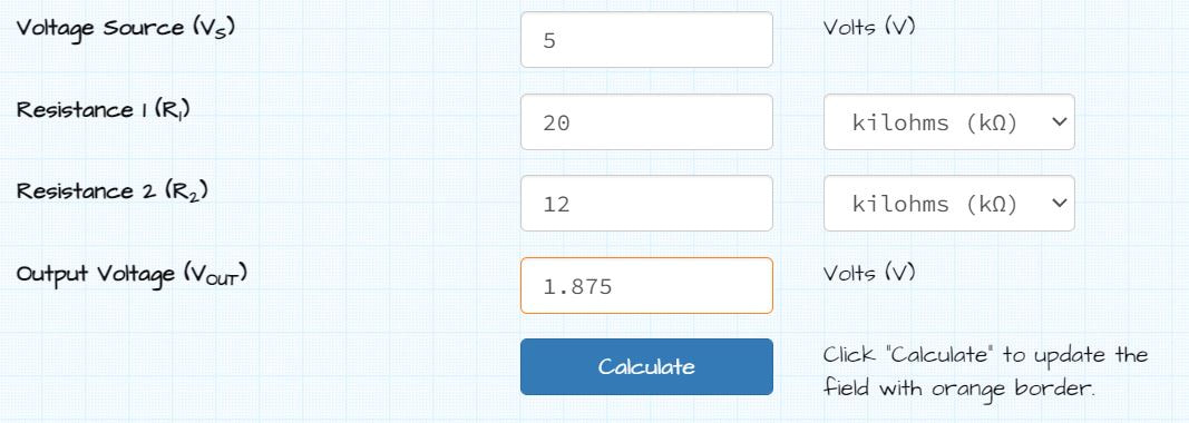
- The resistor divider used for the comparator was set too low. The original setting was 1.66 V, but testing with the SN74LVC1G14 showed it needed to be adjusted to 1.88 V.
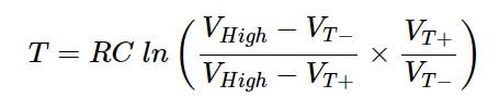
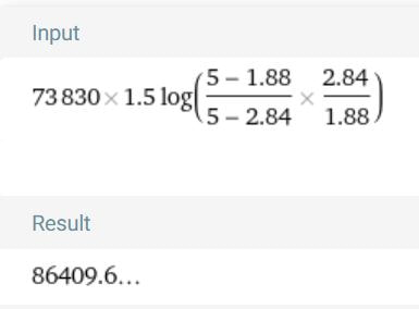
The RC time constant was recalculated using the example from All About Circuits:
https://www.allaboutcircuits.com/technical-articles/exactly-how-schmitt-trigger-oscillators-work/
 All About Circuits
The resistor required to achieve a 24-hour period with the SN74LVC1G14 voltage thresholds and a fixed 1.5 F capacitor is approximately 73.83 kΩ.
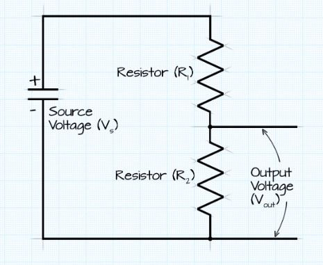
Resistor divider calculation used to charge the capacitor to the low-voltage threshold.
Capturing some waveforms from the accelerated configuation (lower RC time constant). the square wave is visible on the oscilloscope.
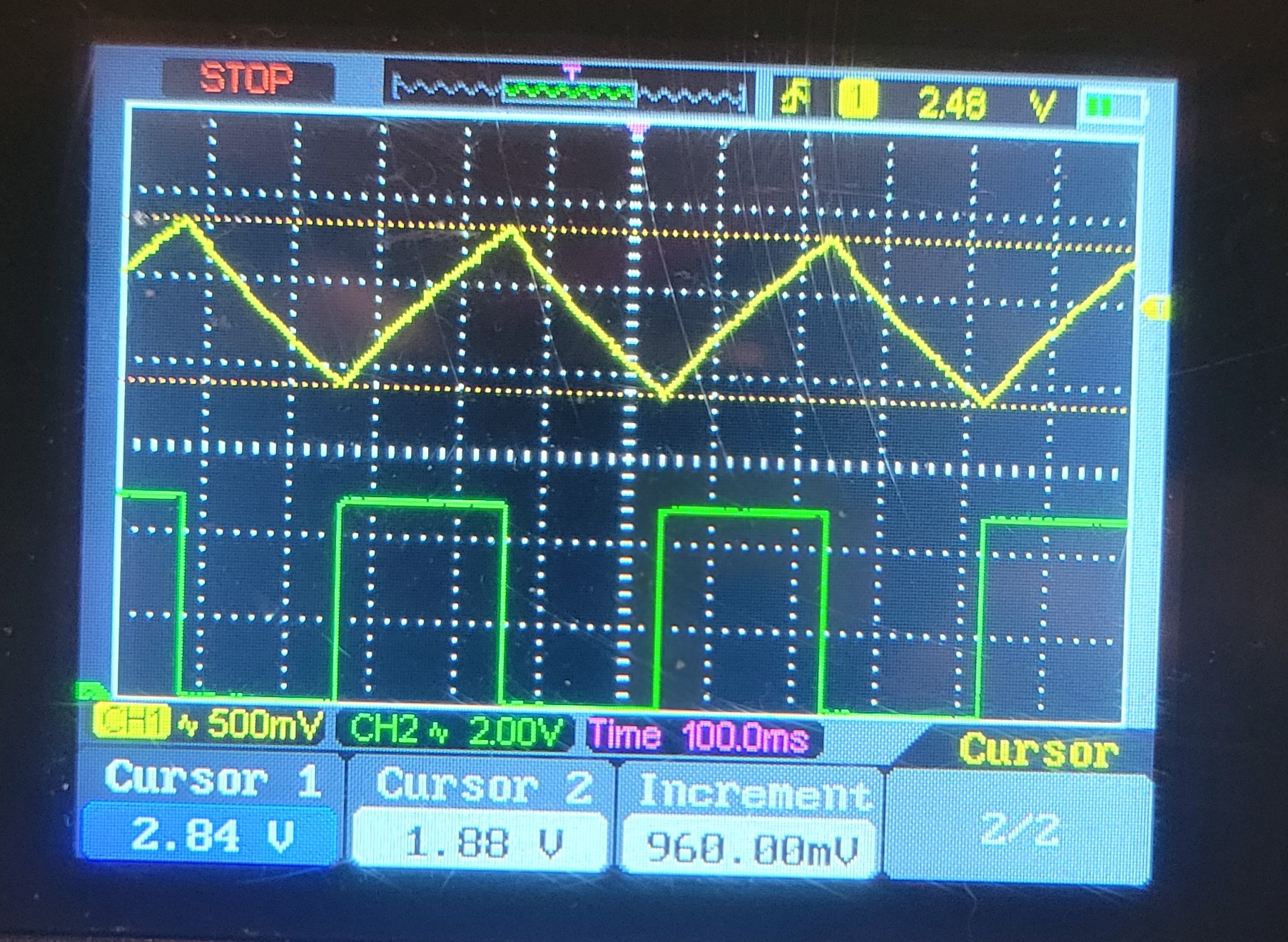
The video below shows the waveform from the accelerated configuration.
Conclusion
After multiple revisions to the circuit, I determined that leakage currents within the components were interfering with the design and causing the long-time-constant circuit to fail, preventing the next LED from incrementing properly. The design works well when the LEDs are incremented manually, and the LEDs themselves look very cool with the built-in flickering feature!
I ultimately concluded that the design would be much easier to implement using a low-cost MCU rather than a purely analog approach. However, I would still like to revisit the idea in the future using an all-analog implementation with additional frequency-divider stages.
← Back to Home
I ultimately concluded that the design would be much easier to implement using a low-cost MCU rather than a purely analog approach. However, I would still like to revisit the idea in the future using an all-analog implementation with additional frequency-divider stages.