Automatic Menorah - V2
The why
After attempting (and failing) to implement the automatic 24-hour timing feature using an analog Schmitt trigger oscillator, I decided it was time to venture into the world of embedded programming.
The design - ATTiny85
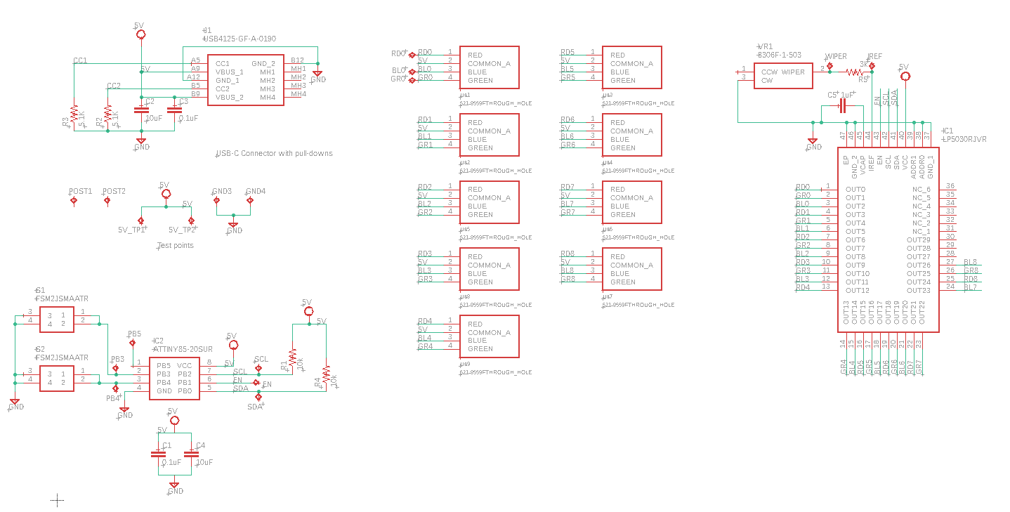
The MCU chosen for the project was the ATTiny85 due to its small code-space requirements and limited number of I/O pins needed to drive the LEDs and interface with a couple of control buttons.
Since the design now included an MCU, I decided to take advantage of its capabilities by driving nine RGB LEDs using the LP5030 LED driver from Texas Instruments. After making several modifications to the LP50XX library created by rneurink, I was able to get the driver functioning reliably.
Implementing the design
The ATTiny85 communicates with the LP5030 LED driver over I2C to control the RGB LEDs independently. Two push buttons were added to provide user interaction: one button manually increments the active candle, while the other activates a rainbow animation mode that cycles through the RGB color spectrum.
The timing logic was implemented using the ATTiny85 hardware timers and counters to track the 24-hour interval between candle increments. When the device is powered on, the timer begins automatically. Manually incrementing a candle resets the timer to maintain synchronization with the desired schedule.
The timing logic was implemented using the ATTiny85 hardware timers and counters to track the 24-hour interval between candle increments. When the device is powered on, the timer begins automatically. Manually incrementing a candle resets the timer to maintain synchronization with the desired schedule.
Results
Using the LP5030 and its RGB capabilities made it relatively easy to simulate realistic fire flickering by dynamically adjusting the RGB intensity percentages. The push buttons provided additional functionality, including a rainbow animation mode that sweeps through the RGB spectrum and a manual increment mode for advancing the active candle.
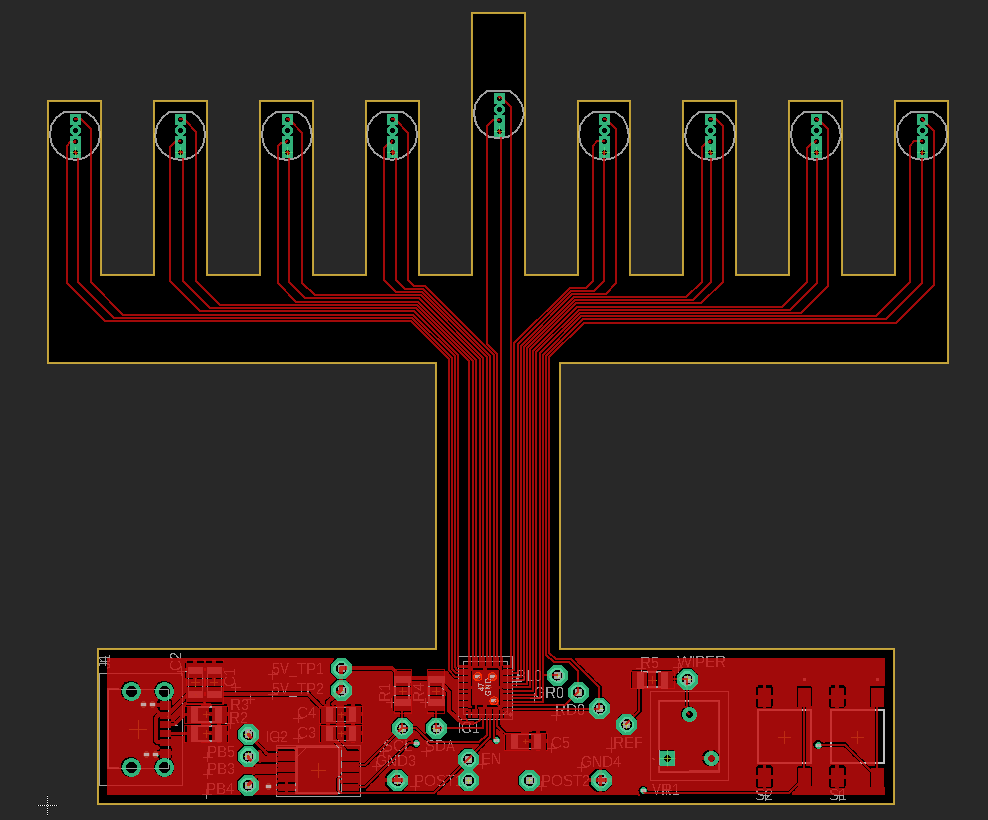
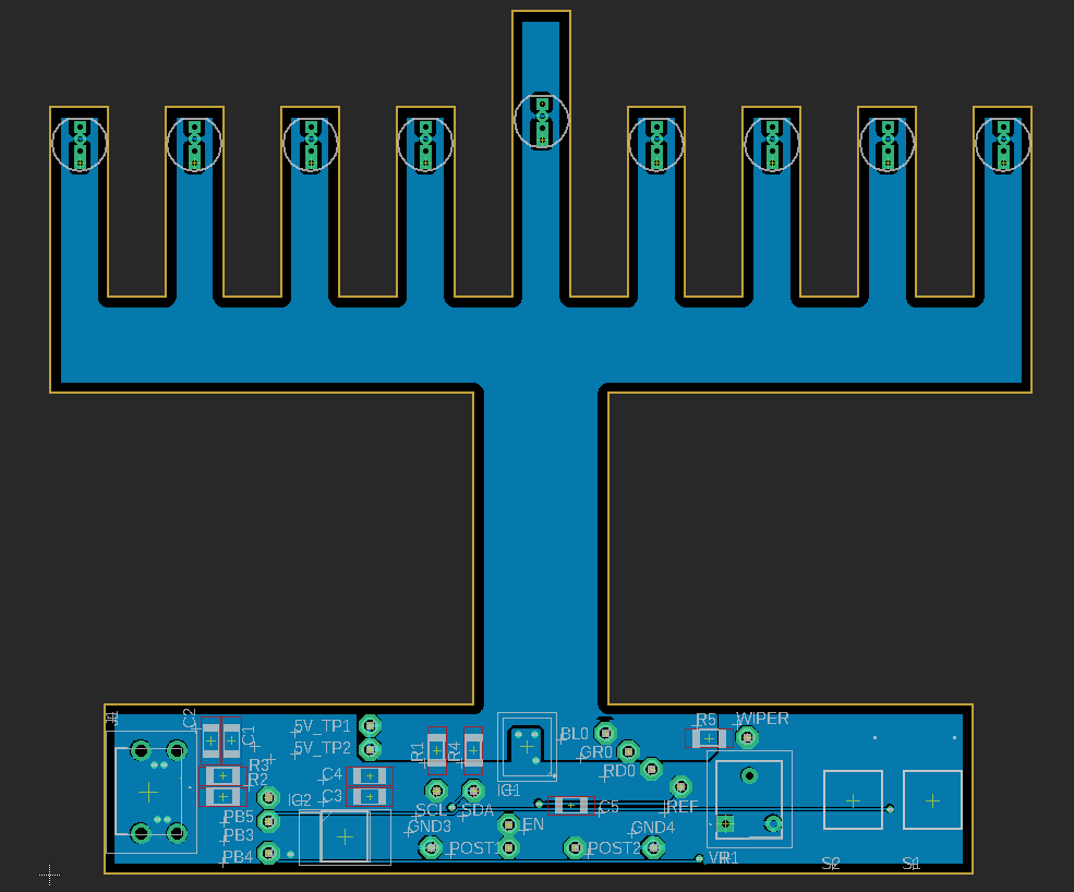
There were some challenges soldering the LP5030 onto the PCB. The boards were not assembled perfectly, and it appears there may be short-circuited pins underneath the IC package, causing some LEDs to display incorrect colors or fail to illuminate properly. Additionally, implementing accurate long-duration timing using the built-in hardware counters proved more difficult than expected.
Of the two assembled units, each appears to exhibit slightly different timing behavior. I suspect this may be related to differences in debug configurations or timer settings saved in non-volatile memory during development. The second unit currently operates with a timing interval longer than 24 hours and still requires additional debugging and calibration.
Conclusion
Using an MCU to implement the design proved to be significantly easier, cheaper, and more space-efficient than the previous all-analog approach. Despite this, the idea of revisiting the project with a fully analog implementation for a future Menorah V3 design is still appealing.
← Back to Home