555 Timer Flashing Heart
Following the guide here: https://www.electroschematics.com/pulse-generator-with-555/
The circuit was built on the breadboard first to test different components for the duty cycle and flashing frequency. The final schematic had a slight error with the R3 orientation (capacitors C1,2,3,4 are on the wrong node.) But the final design still allows some adjustment for frequency and PWM.
This was a small project over a weekend for my girlfriend (now wife).
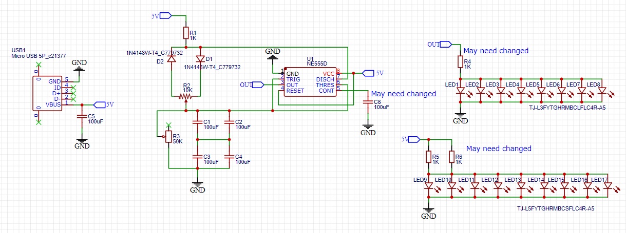
The duty cycle, n, is calculated using the following formula:
n = 1 + R2/R3
To calculate the frequency, the following formula can be used:
f = 0.69/((2*R3 + R2 + 4.7kΩ)*(C1,2,3,4))
n = 1 + R2/R3
To calculate the frequency, the following formula can be used:
f = 0.69/((2*R3 + R2 + 4.7kΩ)*(C1,2,3,4))
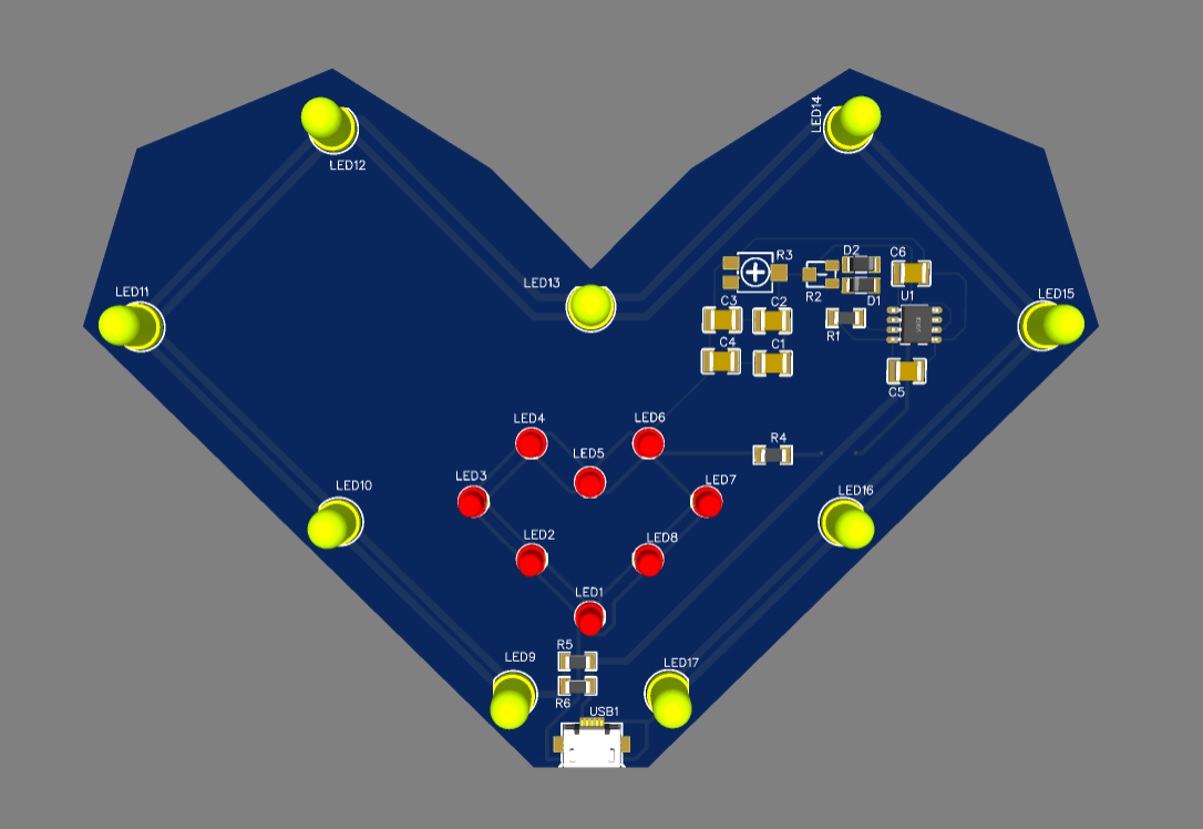
Above is the final design that has adjustable frequency and duty cycle for the center LEDs to flash near a heartbeat's frequency.
← Back to Home