2-Quadrant Power Source and Sink
The Why
When working with batteries, having a power supply which can both sink and source current to simulate a battery is extremely useful. Batteries take a long time to charge and discharge and can be dangerous if you are testing features of a BMS which are not robust yet.
Commercial options like the Keithley SMUs are extremely expensive, and can be overkill for many tests.
Commercial options like the Keithley SMUs are extremely expensive, and can be overkill for many tests.
The Design
The design is intended for single cell battery simulation, or for any general purpose supply needed for sink/source up to approximately 3A and up to 4.7V. The main IC used for this design is the OPA569 power amplifier, which has a low voltage range up to 5.5V and up to 2A sink/source capability. The output voltage is controlled using a potentiometer.
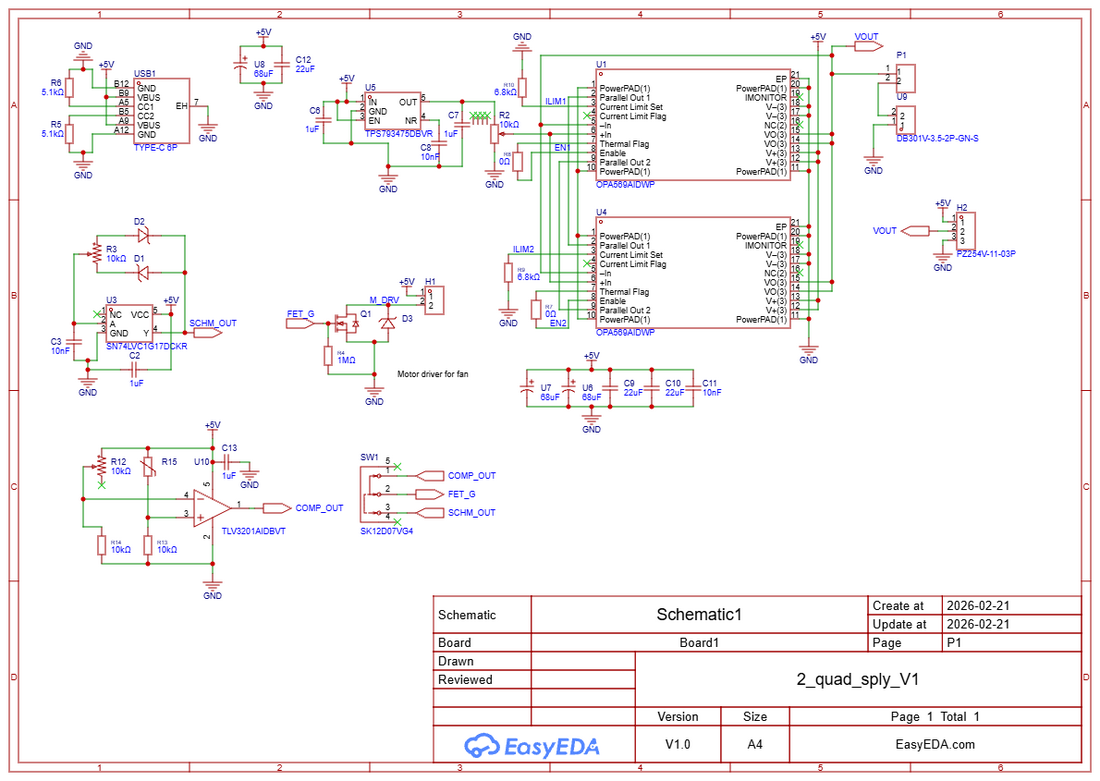
Due to the higher power dissipation, I decided to experiment with a few different options to control the fan speed. One option utilizes a comparator (TLV3201) to trip once a thermistor indicates the temperature is too high. The other option is to use a Schmitt trigger with adjustable PWM in order to have a variable speed fan that remains on all the time. In reality only the comparator with thermistor is really needed, and ended up working well in the final design.
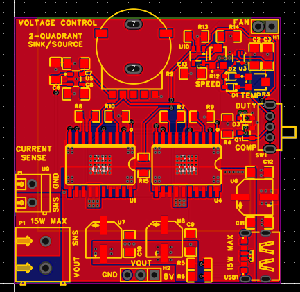 The top layer is signal, GND and power.
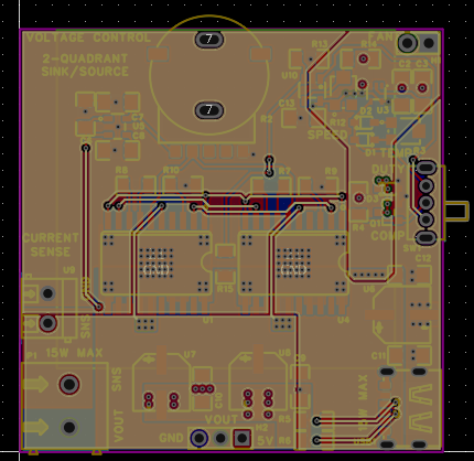 Middle layer 1 is power and GND, some signal.
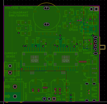 Middle layer 2 is mostly GND, with some power traces.
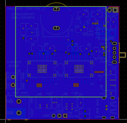 The bottom layer is solid GND to help dissipate heat. The stackup was 0.5oz inner layer copper, and 2oz outer layer to help with heat distribution.
The Results
The results from testing showed that all the different functionality works as designed. The Schmitt trigger oscillator worked great to control the fan speed by adjusting the PWM with a very simple low cost circuit. The comparator also worked great by only turning the fan on when the power amps heat up too much.
The power amplifier section also works well, it is able to sink or source up to 3A, the maximum output voltage is about 4.7V.
← Back to Home